Category Archives: Storage Technology
Deduplication Internals – Source Side & Target Side Deduplication: Part-4
In Continuation of my deduplication series Part 1, Part 2, Part 3, in this part we will discuss where the deduplication happens. Based on where the dedupe process is happening, there is 2 types – That is Source Side or Client side and Target side. These are widely used in the Backup Technology, that is backup software and hardware appliances. Like IBM Tivoli TSM, Symantec backup Exec, EMC Avamar, Netbackup etc.
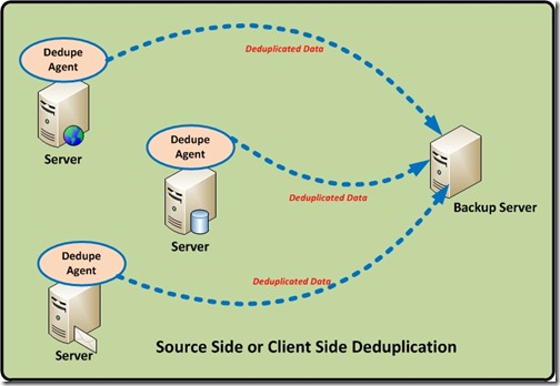
Source or Client Side Deduplication.
From the Name itself we can say, the entire deduplication is happening on the Client (Servers), there will be dedicated deduplication agents installed in the servers and these agents use the CPU/RAM of the server to perform the deduplication. This thereby distributing the deduplication processing overhead across multiple systems.
Source-side deduplication typically uses a client-located deduplication engine that will check for duplicates against a centrally-located deduplication index, typically located on the backup server or media server. Only unique blocks will be transmitted to the disk. So less data to transfer so the backup window is also get reduced.
Source-based deduplication processes the data before it goes over the network. This reduces the amount of data that must be transmitted, which can be important in environments with constrained bandwidth. That is less network bandwidth needed for the backup software.
This method is often used in situations where remote offices must back up data to the primary data center. In this case, deduplication becomes the responsibility of the client server.
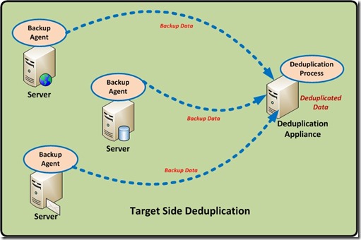
Target Side Deduplication.
Target-based deduplication requires that the target backup server or a dedicated Hardware target dedupe appliance handles all of the deduplication. This means no overhead on the client or server being backed up. This solution is transparent to existing workflows, so it creates minimal disruption. However, it requires more network resources because the original data, with all its redundancy, must go over the network.
So a target deduplication solution is a purpose built appliance, so the hardware and software stack are tuned to deliver optimal performance, so there is no additional CPU/RAM resource usage in the client servers.
Dell DR4000, Symantec NetBackup PureDisk, Symantec NetBackup 5220, EMC Avamar, HP StoreOnce, EMC’s Data Domain, ExaGrid Systems’ DeltaZone and NEC’s Hydrastor, IBM’s ProtecTier and Sepaton’s DeltaStor, Quantum DXi are the main examples which uses this type of deduplication.
My next post will be about the Inline and Post processing deduplication………!! Stay Tuned !!!
Deduplication Internals – Content Aware deduplication : Part-3
Continuation to my previous part 1 and part 2 in this part we will discuss about the Content aware or Application Aware deduplication.
This type of deduplication is generally called a Byte level deduplication, because the deuplication for the information happens in the deepest level – that is BYTES.
Content aware technologies (also called byte level deduplication or delta-differencing deduplication ) work in a fundamentally different way. Key element of the content-aware approach is that it uses a higher level of abstraction when analyzing the data. Content-aware de-duplication looks at the data as objects. Unlike hash based dedupe, which try to find redundancies in block level, content-aware looks it as objects, comparing them to other objects. (e.g., Word document to Word document or Oracle database to Oracle database.)
In this, the deduplication engine sees the actual objects (files, database objects, application objects etc.) and divides data into larger segments (usually 8mb to 100mb in size). Then, typically by using knowledge of the content of the data (known as being “content-aware”), this technique finds segments that are similar and stores only the changed bytes between the objects. That is a BYTE level comparison is performed.
If we look in to detail, In this type before the dedupe process, an unique metadata is typically inserted within the data types,like database, email, photo, documents etc. Then during the dedupe process, this metadata for the data block is extracted and examined to understand what kind of data present in the block. Based on the type of data , a certain block size is assigned to that particular data, and the block size is optimized based on the type of data being backed up.
Since the block size is already optimized for that particular data type, CPU cycles don’t need to be wasted to determine the block boundaries. Compare to other deduplication techniques (hash based), where the data is blindly chopped to find the boundaries, that is to find the block length and then identify duplicate segments.
The below example will give more insight to this;
I have saved a photo, then open it and edited one pixel and save the new version as a new file, there won’t be a single duplicate block at the disk level. On the other hand, almost the entire file is a duplicate information. Can you find a duplicate graphic that was used in a Powerpoint, a Word document, and a PDF? Powerpoint and Word both compress with a variant of zip. Even if the graphic is identical, block level dedupe won’t find the duplicate graphics because they are not stored identically on disk. You need something that can find duplicate data at the information level, the answer is – Content Aware or Application Aware dedupe solutions.
This approach provides a good balance between performance and resource utilization.
CommVault Simpana, Symantec Backup exec, Symantec netbackup, Dell DR4000, Sepaton’s DeltaStor, Exagrid are the solutions which use this technology.
Deduplication Internals – Hash based deduplication : Part-2
Now in the second part we discuss about the process or technique used to do the deduplication.
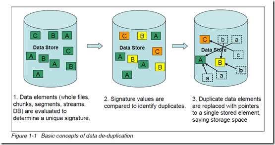
Different data de-duplication products use different methods of breaking up the data into elements or chunks or blocks, but each product uses some technique to create a signature or identifier or fingerprint for each data element. As shown in the below figure, the data store contains the three unique data elements A, B, and C with a distinct signature. These data element signature values are compared to identify duplicate data. After the duplicate data is identified, one copy of each element is retained, pointers are created for the duplicate items, and the duplicate items are not stored.
The basic concepts of data de-duplication are illustrated in below.
Based on the Technologies, or how how it is done. Two methods frequently used used for de-duplicating data are hash based and content aware.
1 – Hash based Deduplication
Hash based data de-duplication methods use a hashing algorithm to identify “chunks” of data. Commonly used algorithms are Secure Hash Algorithm 1 (SHA-1) and Message-Digest
Algorithm 5 (MD5). When data is processed by a hashing algorithm, a hash is created that represents the data. A hash is a bit string (128 bits for MD5 and 160 bits for SHA-1) that
represents the data processed. If you processed the same data through the hashing algorithm multiple times, the same hash is created each time.
Here are some examples of hash codes:
MD5 – 16 byte long hash
– # echo “The Quick Brown Fox Jumps Over the Lazy Dog” | md5sum
9d56076597de1aeb532727f7f681bcb0
– # echo “The Quick Brown Fox Dumps Over the Lazy Dog” | md5sum
5800fccb352352308b02d442170b039d
SHA-1 – 20 byte long hash
– # echo “The Quick Brown Fox Jumps Over the Lazy Dog” | sha1sum
F68f38ee07e310fd263c9c491273d81963fbff35
– # echo “The Quick Brown Fox Dumps Over the Lazy Dog” | sha1sum
d4e6aa9ab83076e8b8a21930cc1fb8b5e5ba2335
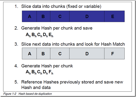
Hash based de-duplication breaks data into “chunks”, either fixed or variable length, and processes the “chunk” with the hashing algorithm to create a hash. If the hash already exists, the data is deemed to be a duplicate and is not stored. If the hash does not exist, then the data is stored and the hash index is updated with the new hash.
In Figure 1-2, data “chunks” A, B, C, D, and E are processed by the hash algorithm and creates hashes Ah, Bh, Ch, Dh, and Eh; for purposes of this example, we assume this is all new data.
Later, “chunks” A, B, C, D, and F are processed. F generates a new hash Fh. Since A, B, C, and D generated the same hash, the data is presumed to be the same data, so it is not stored again. Since F generates a new hash, the new hash and new data are stored.
A – Fixed-Length or Fixed Block
In this data deduplication algorithm, it breaks the Data in to chunks or block, and the block size or block boundaries is Fixed like 4KB, or 8KB etc. And the block size never changes. While different devices/solutions may use different block sizes, the block size for a given device/solution using this method remains constant.
The device/solution always calculates a fingerprint or signature on a fixed block and sees if there is a match. After a block is processed, it advances by exactly the same size and take another block and the process repeats.
Advantages
Requires the minimum CPU overhead, and fast and simple
Disadvantages
Because the block size or block boundaries is Fixed, the main limitation of this approach is that when the data inside a file is shifted, for example, when adding a slide to a Microsoft PowerPoint deck, all subsequent blocks in the file will be rewritten and are likely to be considered as different from those in the original file. Smaller block size give better deduplication than large ones, but it takes more processing to deduplicate. Larger block size give low depulication, but it takes less processing to deduplicate.
So the Bottom line is Less storage savings and not efficient.
B – Variable-Length or Variable Block
In this data deduplication algorithm, it breaks the Data in to chunks or block, and the block size or block boundaries is variable like 4KB, or 8KB or 16KB etc. And the block size changes dynamically during the entire process. The device/solution always calculates a fingerprint or signature on a variable block size and sees if there is a match. After a block is processed, it advances by taking another block size and take another blocks and the process repeats.
Advantages
Higher deduplication ratio, high storage space savings.
Disadvantages
While the variable block deduplication may yield slightly better deduplication than the fixed block deduplication approach, it does require you to pay a price. The price being the CPU cycles that must be spent in trying to determine the file boundaries. The variable block approach requires more processing than fixed block because the whole file must be scanned, one byte at a time, to identify block boundaries.
Check out the following example based on the following sentence will explain in detail: “deduplication technologies are becoming more an more important now.”
Notice how the variable block deduplication has some funky block sizes. While this does not look too efficient compared to fixed block, check out what happens when I make a correction to the sentence. Oops… it looks like I used ‘an’ when it should have been ‘and’. Time to change the file: “deduplication technologies are becoming more and more important now.” File –> Save
After the file was changed and deduplicated, this is what the storage subsystem saw:
The red sections represent the changed blocks that have changed. By adding a single character in the sentence, a ‘d’, the sentence length shifted and more blocks suddenly changed. The Fixed Block solution saw 4 out of 9 blocks changed. The Variable Block solution saw 1 out of 9 blocks changed.
Variable block deduplication ends up providing a higher storage density and good storage space savings.
2 – Content Aware or application-aware Deduplication
My next blog will be about the content aware dedupe.
Deduplication Internals : Part-1
Deduplication is one of the hottest technologies in the current market because of its ability to reduce costs. But it comes in many flavours and organizations need to understand each one of them if they are to choose the one that is best for them. Deduplication can be applied to data in primary storage, backup storage, cloud storage or data in flight for replication, such as LAN and WAN transfers. So eventually it offers the below benefits;
– Allow to substantially save disk space, reduce storage requirements and Less hardware
– Improve bandwidth efficiency,
– Improve replication speed,
– Reduce Backup window and improve RTO and RPO objectives,
– and finally COST.
What is data deduplication?
This concept is a familiar one which we see daily, a URL is a type of pointer; when someone shares a video on YouTube, they send the URL for the video instead of the video itself. There’s only one copy of the video, but it’s available to everyone. Deduplication uses this concept in a more sophisticated, automated way.
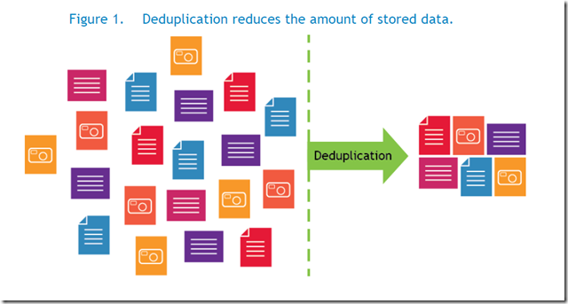
Data deduplication is a technique to reduce storage needs by eliminating redundant or duplicate data in your storage environment. Only one and unique copy of the data is retained on storage media, and redundant or duplicate data is replaced with a pointer to the unique data copy.
That is, It looks at the data on a sub-file (i.e.block) level, and attempts to determine if it’s seen the data before. If it hasn’t, it stores it. If it has seen it before, it ensures that it is stored only once, and all other references to that duplicate data are merely pointers.
How data deduplication works?
Dedupe technology typically divides data in to smaller chunks/blocks and uses algorithms to assign each data chunk a unique hash identifier called a fingerprint to each chunks/blocks. To create the fingerprint, it uses an algorithm that computes a cryptographic hash value from the data chunks/blocks, regardless of the data type. These fingerprints are stored in an index.
The deduplication algorithm compares the fingerprints of data chunk/block to those already in the index. If the fingerprint exists in the index, the data chunk/block is replaced with a pointer to data chunk/block. If the fingerprint does not exist, the data is written to the disk as a new unique data chunk.
Different types of de-duplication – There are many types and broad classification of dedupe methods; they are
1- Based on the Technologies, how it is done.
Fixed-Length or Fixed Block Deduplication
Variable-Length or Variable Block Deduplication
Content Aware or application-aware deduplication
2- Based on the Process, or when it is done.
In-line (or as I like to call it, synchronous) de-duplication
Post-process (or as I like to call it, asynchronous) de-duplication
3- Based on the Type, or where it happens.
Source or Client side Deduplication
Target Deduplication
My next post will discuss, in detail about these dedupe technologies and process.
Magic Effect of SIOC (VMware Storage Input Output Control) in vSphere 5 : A practical study.
Recently I got a chance to implement and test the Enterprise Plus feature in vSphere called SIOC. It is really an amazing feature…..
Theory
Application performance can be impacted when servers contend for I/O resources in a shared storage environment. There is a crucial need for isolating the performance of critical applications from other, less critical workloads by appropriately prioritizing access to shared I/O resources. Storage I/O Control (SIOC), a new feature offered in VMware vSphere 4 & 5, provides a dynamic control mechanism for managing I/O resources across VMs in a cluster.
Datacenters based on VMware’s virtualization products often employ a shared storage infrastructure to service clusters of vSphere hosts. NFS, ISCSI, and Storage area networks (SANs) expose logical storage devices (LUNs) that can be shared across a cluster of ESX hosts. Consolidating VMs’ virtual disks onto a single VMFS datastore, or NFS datastore, backed by a higher number of disks has several advantages—ease of management, better resource utilization, and higher performance (when storage is not bottlenecked).
With vSphere 4.1 we can only use SIOC with FC/ISCSI datastores, but with vSphere 5 we can use NFS.
However, there are instances when a higher than expected number of I/O-intensive VMs that share the same storage device become active at the same time. During this period of peak load, VMs contend with each other for storage resources. In such situations, lack of a control mechanism can lead to performance degradation of the VMs running critical workloads as they compete for storage resources with VMs running less critical workloads.
Storage I/O Control (SIOC), provides a fine-grained storage control mechanism by dynamically allocating portions of hosts’ I/O queues to VMs running on the vSphere hosts based on shares assigned to the VMs. Using SIOC, vSphere administrators can mitigate the performance loss of critical workloads during peak load periods by setting higher I/O priority (by means of disk shares) to those VMs running them. Setting I/O priorities for VMs results in better performance during periods of congestion.
So What is the Advantage for an VM administrator/Organization? Now a days, with vSphere 5 we can have 64TB of single LUN and with high end SAN with FLASH we are achieving more consolidation. That’s great !! but when we do this…. just like the CPU/MEMORY resource pools ensure the Computing SLA, the SIOC ensures the virtual disk STORAGE SLA and its response time.
In short, below are the benefits;
– SIOC prioritizes VMs’ access to shared I/O resources based on disk shares assigned to them. During the periods of I/O congestion, VMs are allowed to use only a fraction of the shared I/O resources in proportion to their relative priority, which is determined by the disk shares.
– If the VMs do not fully utilize their portion of the allocated I/O resources on a shared datastore, SIOC redistributes the unutilized resources to those VMs that need them in proportion to VMs’ disk shares. This results in a fair allocation of storage resources without any loss in their utilization.
– SIOC minimizes the fluctuations in performance of a critical workload during periods of I/O congestion, as much as a 26% performance benefit compared to that in an unmanaged scenario.
How Storage I/O Control Works
SIOC monitors the latency of I/Os to datastores at each ESX host sharing that device. When the average normalized datastore latency exceeds a set threshold (30ms by default), the datastore is considered to be congested, and SIOC kicks in to distribute the available storage resources to virtual machines in proportion to their shares. This is to ensure that low-priority workloads do not monopolize or reduce I/O bandwidth for high-priority workloads. SIOC accomplishes this by throttling back the storage access of the low-priority virtual machines by reducing the number of I/O queue slots available to them. Depending on the mix of virtual machines running on each ESX server and the relative I/O shares they have, SIOC may need to reduce the number of device queue slots that are available on a given ESX server.
It is important to understand the way queuing works in the VMware virtualized storage stack to have a clear understanding of how SIOC functions. SIOC leverages the existing host device queue to control I/O prioritization. Prior to vSphere 4.1, the ESX server device queues were static and virtual-machine storage access was controlled within the context of the storage traffic on a single ESX server host. With vSphere 4.1 & 5, SIOC provides datastore-wide disk scheduling that responds to congestion at the array, not just on the hostside HBA.. This provides an ability to monitor and dynamically modify the size of the device queues of each ESX server based on storage traffic and the priorities of all the virtual machines accessing the shared datastore. An example of a local host-level disk scheduler is as follows:
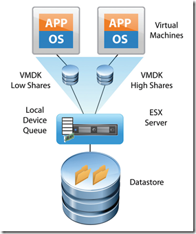
Figure 1 shows the local scheduler influencing ESX host-level prioritization as two virtual machines are running on the same ESX server with a single virtual disk on each.
Figure 1. I/O Shares for Two Virtual Machines on a Single ESX Server (Host-Level Disk Scheduler)
In the case in which I/O shares for the virtual disks (VMDKs) of each of those virtual machines are set to different values, it is the local scheduler that prioritizes the I/O traffic only in case the local HBA becomes congested. This described host-level capability has existed for several years in ESX Server prior to vSphere 4.1 & 5. It is this local-host level disk scheduler that also enforces the limits set for a given virtual-machine disk. If a limit is set for a given VMDK, the I/O will be controlled by the local disk scheduler so as to not exceed the defined amount of I/O per second.
vSphere 4.1 onwards it has added two key capabilities: (1) the enforcement of I/O prioritization across all ESX servers that share a common datastore, and (2) detection of array-side bottlenecks. These are accomplished by way of a datastore-wide distributed disk scheduler that uses I/O shares per virtual machine to determine whether device queues need to be throttled back on a given ESX server to allow a higher-priority workload to get better performance.
The datastore-wide disk scheduler totals up the disk shares for all the VMDKs that a virtual machine has on the given datastore. The scheduler then calculates what percentage of the shares the virtual machine has compared to the total number of shares of all the virtual machines running on the datastore. As described before, SIOC engages only after a certain device-level latency is detected on the datastore. Once engaged, it begins to assign fewer I/O queue slots to virtual machines with lower shares and more I/O queue slots to virtual machines with higher shares. It throttles back the I/O for the lower-priority virtual machines, those with fewer shares, in exchange for the higher-priority virtual machines getting more access to issue I/O traffic.
However, it is important to understand that the maximum number of I/O queue slots that can be used by the virtual machines on a given host cannot exceed the maximum device-queue depth for the device queue
of that ESX host.
What are the conditions required for the SIOC to work ?
– A large datastore, and lot of VMs in it and this datastore is shared between multiple ESX hosts.
– Need to set disk shares, for the vm’s inside the datastore.
– Based on the LUN/NFS type (made of SSD,SAS,SATA), select the SIOC threshold, and enable SIOC.
– The SIOC will monitor the datastore IOPS usage, latency of VM’s and monitor overall STORAGE Array performance/Latency.
SIOC don’t check the below;
How much Latency created by other physical systems to the array, that is the Array is shared for the PHYSICAL hosts also, and other backup applications/jobs etc. So it gives false ALARMS like “VMware vCenter – Alarm Non-VI workload detected on the datastore] An unmanaged I/O workload is detected on a SIOC-enabled datastore”
Tricky Question – Will it work for one ESXi host ? Simple answer – SIOC is for multiple ESXi hosts, Datastore is exposed to many hosts and in that Datastore contains a lot of VM’s. For single host also we can enable the SIOC if we have the license, but it is not intended for this CASE.
So what is the solution for a single ESXi host ? – Simple just use shares for the VMDK and the ESXi host use Host-Level Disk Scheduler and ensures the DISK SLA.
So is there any real advantage of the SIOC in Real time scenario ? the below experience of me PROVES this..
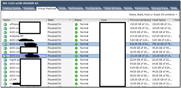
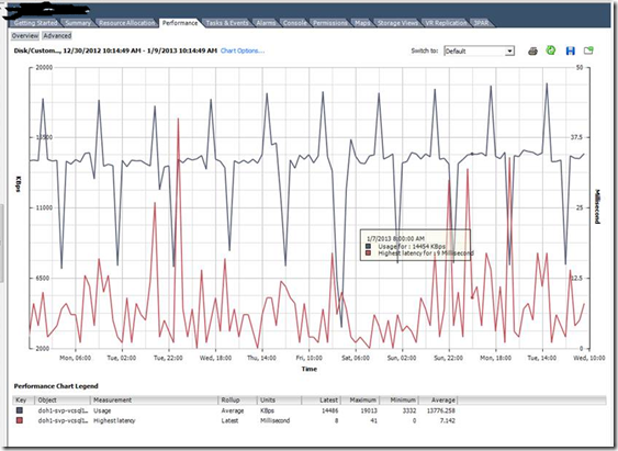
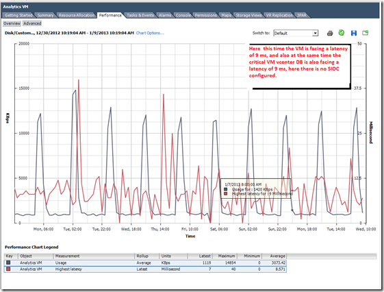
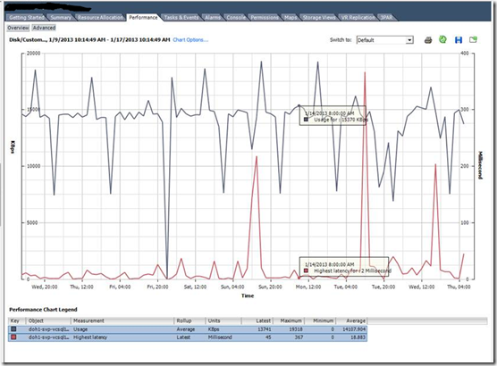
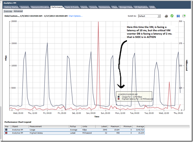
My scenario: I have 4 ESXi 5 hosts in the cluster, and many FC LUNS from the HP 3PAR storage arrays is mounted. In one or the LUN we have put around 16 VMs and this includes our vCenter and it Database, and inside that Datastore we have a less critical VM (Analytics engine, which is from the vCOPS appliance) and this consumes a lot of IOPS from the storage and eventually effects other critical VM. We enabled the SIOC and monitored for 10 days then we compared the performance of the VMDK and its LATENCY during the PEAK hours.
Below is the Datastore with many VMS and it is shared across 4 HOSTS.
With SIOC disabled.
With SIOC enabled.
So what is the Take away with SIOC ?
Better I/O response time, reduced latency for critical VMS and ensured disk SLA for critical VM’s. So bottom line is the crtical VM’s wont get affected during the event of storage contention and in highly consolidated environment.
REFERENCES:
http://blogs.vmware.com/vsphere/2012/03/debunking-storage-io-control-myths.html
http://blogs.vmware.com/vsphere/2011/09/storage-io-control-enhancements.html
http://www.vmware.com/files/pdf/techpaper/VMW-vSphere41-SIOC.pdf
Partition alignment in VMware vSphere 5, a DeepDrive, Part-2
In continuation to my part-1, we will see how the Virtual machine disk alignment effects the Virtualized world and eventually the performance.
Here we need to know how to align the disk partitions in OS like windows 2003, XP, RHEL 5.x etc in VMware vSphere VMFS 5 Datastore.
Let us assume the VMFS is residing above a RAID volume or a LUN from a storage array, in either case the RAID STRIP size will be from 4KB to 256KB depending upon the ARRAY and RAID levels. So now we are deployed the above mentioned operating systems on the VMFS,
What is the ISSUE with the GUEST OS disk misalignment ?
This issue is applicable to the PHSICAL and VIRTUAL also and it is not because of the VMFS layer or any other means. It is the limitation of these OS and how they do the partition in the given HDD, just like to the PHYSICAL world, in VIRTUAL world the Hypervisor also gives an HDD but it is a VIRTUAL HDD. But the OS doesn’t know if it is a virtual HDD or Actual HDD. So eventually the OS wont do the partition with correct alignment.
Leave the VITRUL world and go to PHYSICAL world, let us assume the Guest filesystem Block/Cluster is 4KB, and it writes or reads a 4KB to the hard disk, and in turn it goes to the HDD PHYSICAL sector of 4KB. Because the partition is not ALIGNED it uses 2 PHYSICAL sectors of 4KB for this operation, here the amount of Data read/write is same but it uses 2 PHYSICAL sectors.
So the Harddisk HEAD need to do more work to fetch the Data to and from the PHYSICAL sectors. So for a single IO for the same 4KB data from the OS, the HDD or Array need to use 2 PHYSICAL sectors, so the IOPS response time and latency will be affected. So we will get a POOR performance. This is applicable in VIRTUAL world also,
As of now the VMFS3 and VMFS5 are already aligned to the underlying storage. The below give more info how the VMFS is aligned, open an ESXi shell or SSH and type the below;
~ # partedUtil get /vmfs/devices/disks/naa.600508b1001030394330313737300300
71380 255 63 1146734896
1 2048 1146719699 0 0
~ #
The first line displayed is disk geometry information (cylinders, heads, sectors per track and LBA [Logical Block Address] count). The second line is information about the partitions. There is only 1 partition; it starts at LBA 2048 and ends at LBA 1146719699.That’s something else to be aware of – newly created VMFS-5 partitions start at LBA 2048. This is different to previous versions of VMFS:
- VMFS-2 created on ESX 2.x; starting LBA 63
- VMFS-3 created on ESX 3 & 4; starting LBA 128
- VMFS-5 created on ESXi 5; starting LBA 2048
So the VMFS is aligned with the 1MB boundary (starts from the LBA 2048), and as we all know the VMFS 5 the block size is 1MB. So the VMFS and the underlying storage is already aligned. So when a misaligned GUEST OS send’s a READ/WRITE request to the HYPERVISOR layer, that is from the VMDK to the VM SCSI controller to the VMFS and finally to the STORAGE, the STORAGE has to look for more than one PHYSICAL sector or CHUNK, this is an over head for the storage and of course it will be an over head to the VMkernel, because the VMkernel has to wait until the array does the task.
If the GUEST OS is aligned, for one 4KB write/read it will use only one single CHUNK from the storage, this will give GOOD Response time and LOW latency for the IOPS operation.
Now How to align the Guest OS;
For windows follow the below –
1- Add the required virtual HDD to the Guest OS
2- Verify the HDD is visible in the OS
3- Open Command prompt and use the Command Line Syntax below
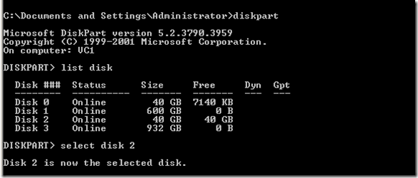
C:\>diskpart
DISKPART> list disk
DISKPART> select disk 2
Disk 2 is now the selected disk.
DISKPART> create partition primary align=1024
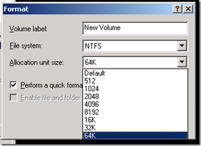
After this format the PARTITON, Windows MSSQL databases and Exchange servers, it is recommended to format the NTFS cluster size as 64K (64 kilobytes) and for other normal server we can use 32K.
Generally to check a partition is aligned or not use the below command, then refer the PART 1 of this blog to do the MATH.
wmic partition get BlockSize, StartingOffset, Name, Index
In my case this shows both my disks having partitions that are aligned to 1024KB or 1MB …or sector2048.
(1048576 bytes)/(512 bytes/sector) = 2048 sector
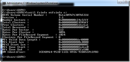
To check File Allocation Unit Size – Run this command for each drive to get the file allocation unit size:
fsutil fsinfo ntfsinfo c:
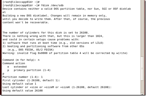
Steps to align the partition for Linux.
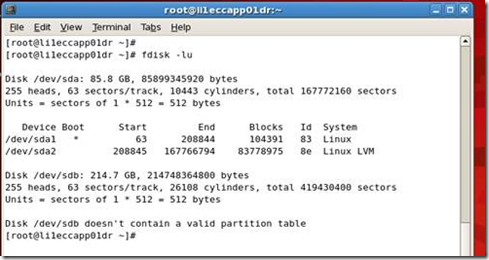
To check that your existing partitions are aligned, issue the command:
fdisk –lu
The output is similar to:
1. Enter fdisk /dev/sd<x> where <x> is the device suffix.
2. Type n to create a new partition.
3. Type p to create a primary partition.
4. Type 1 to create partition No. 1.
5. Select the defaults to use the complete disk.
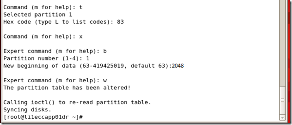
1. Type t to set the partition’s system ID.
2. Type 8e to set the partition system ID to 8e (Linux LVM)
3. Type x to go into expert mode.
4. Type b to adjust the starting block number.
5. Type 1 to choose partition 1.
6. Type 2048 to set it to start with the sector 2048.
7. Type w to write label and partition information to disk.
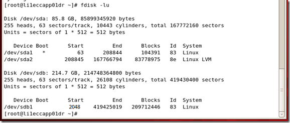
To check that your existing partitions are aligned, issue the command:
fdisk –lu
Now you can see the partition are aligned, that is started from the sector 2048 that is 1MB boundary.
NOTE:
Now in the internet there are many methods to automate the process during the TEMPLATE deployment, one method is add few 1 GB VMDK and do the partition alignment and make a template and after that when the template deployment is over, increase the VMDK for the guest OS. This will work fine for the thin disk and lazy zeroed disks, but if you do the same process for a EAGAR ZEROED disk, then we all know the outcome. Once you increase the EAGAR ZEROED disk it will become LAZY zeroed disk, so for FT and windows clusters, oracle clusters it will be a problem. Else after the VMDK increase you need to use the VMKFSTOOLS to change the VMDK from LAZY zeroed disk to EAGAR ZEROED disk. So again a management overhead, so its your decision !!
REFERENCE:
http://blogs.vmware.com/vsphere/2011/08/vsphere-50-storage-features-part-7-gpt.html
Partition alignment in VMware vSphere 5, a DeepDrive, Part-1
This topic has been discussed seriously for a long time… in the virtualization domain. I would like to add few insights in to this topic, with the new vSphere 5.x release there are lot of changes happened in the VMFS filesystem and also with the release of Windows 2008, 2008 R2, 2012 and RHEL 6.x, Ubuntu 12.x there is no need of doing partition alignment, but it would be good to know how these OS do the partition and handle the disk volumes.
Also the legacy OS like Windows 2003, RHEL 5.x still need partition alignment with vSpehere 5 & VMFS 5 filesystem. In short, generally this topic applies to physical, other hypervisor vendors and to VMWARE also.
There are many outdated articles in the web and below info will give a good insight to this topic.
Theory & History
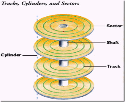
As we all know a physical server or Storage array need physical HDD’s, with virtual machine it is a virtual HDD. The below image shows the hard disk geometry
In the case of early IDE/ATA hard disks the BIOS provides access to the hard disk through an addressing mode called Cylinder-head-sector, also known as CHS, was an early method for giving addresses to each physical block of data on a hard disk drive. CHS addressing is the process of identifying individual sectors on a disk by their position in a track, where the track is determined by the head and cylinder numbers.
In old computer system the maximum amount of addressable data was very limited – due to limitations in both the BIOS and the hard disk interface. The legacy OS like NT, DOS etc uses this method.
Modern hard disks use a recent version of the ATA standard, such as ATA-7. These disks are accessed using a different addressing mode called: logical block addressing or LBA involves a totally new way of addressing sectors. Instead of referring to a cylinder, head and sector number, each sector is instead assigned a unique “sector number”. In essence, the sectors are numbered 0, 1, 2, etc. up to (N-1), where N is the number of sectors on the disk. So all modern disk drives are now accessed using Logical Block Addressing (LBA) scheme where the sectors are simply addressed linearly from 0 to some maximum value and disk partition boundaries are defined by the start and end LBA address numbers. In LBA addressing system with each cylinder standardized to 255 heads, each head has one track with 63 logical blocks or sectors and each one has 512 bytes. You can see this info in linux
All the modern OS uses the LBA method to read/write data to the Harddisk.
In olden days the physical sector of the HDD is 512-byte, and this has been the standard for over 30 years. This physical sector size will match with the size of one Logical block or sector of the OS that is 512 byte, so no issue. During 2009, IDEMA (The International Disk Drive Equipment and Materials Association) and leading data storage companies introduced Advanced Format (AF) Technology in the HDD, so that the physical sector size will be 4K (4,096 bytes). Disk drives with larger physical sectors allow enhanced data protection and correction algorithms, which provide increased data reliability. Larger physical sectors also enable greater format efficiencies, thereby freeing up space for additional user data.
One of the problems of introducing this change in the media format is the potential for introducing compatibility issues with existing software and hardware. As a temporary compatibility solution, the storage industry is initially introducing disks that emulate a regular 512-byte sector disk, but make available info about the true sector size through standard ATA and SCSI commands. As a result of this emulation, there are, in essence, two sector sizes:
Logical sector: The unit that is used for logical block addressing for the media. We can also think of it as the smallest unit of write that the storage can accept. This is the “emulation.”
Physical sector: The unit for which read and write operations to the device are completed in a single operation. That is the Actual physical sector size of storage data on a disk.
Initial types of large sector media
The storage industry is quickly ramping up efforts to transition to this new Advanced Format type of storage for media having a 4 KB physical sector size. Two types of media will be released to the market:
4 KB native: Disks that directly report a 4 KB logical sector size and have a physical sector size of 4 KB – The disk can accept only 4 KB IOs to the disks. However, the software stack can provide 512-byte logical sector size support through RMW support. This media has no emulation layer and directly exposes 4 KB as its logical and physical sector size. The overall issue with this new type of media is that the majority of apps and operating systems do not query for and align I/Os to the physical sector size, which can result in unexpected failed I/Os.
512-byte emulation (512e): Disks that directly report a 512-byte logical sector size but have a physical sector size of 4 KB – Firmware translate 512 byte writes to 4k writes RMW (Read Modify Write). In today’s drives, this translation introduces a performance penalty. This media has an emulation layer as discussed in the previous section and exposes 512-bytes as its logical sector size (similar to a regular disk today), but makes its physical sector size info (4 KB) available.
Overall Windows support for large sector (4KB) media
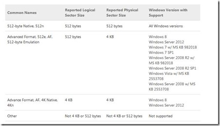
This table documents the official Microsoft support policy for various media and their resulting reported sector sizes. See this KB article for details.
Windows 8, windows server 2012 and Starting with Linux Kernel Version 2.6.34 has full support to read and write 4K for the LBA by the OS. Operating systems like Windows 7, 2008, 2008 R2 still uses 512 Bytes for each logical block or sector, so one physical sector of 4K contains 8 logical sectors of size 512 Bytes.
512-byte emulation at the drive interface
To maintain compatibility, Western Digital, Hitachi, Toshiba emulates a 512-byte device by maintaining a 512-byte sector at the drive interface that is the firmware inside the HDD controller will do the conversion; and Seagate uses SmartAlign technology, for this emulation (firmware level). These drives are also called Advanced Format 512e. Let see how this works !!!
512-byte Read
When the host requests to read a single 512-byte logical block, the hard drive will actually read the entire 4K physical sector containing the requested 512 bytes. The 512-byte block is extracted and sent to the host. This can be done very quickly.
512-byte Write (Read-Modify-Write)
When the host attempts to write a single 512-byte logical block, the hard drive will first read the 4K physical sector containing the 512 bytes that are to be overwritten. Next, it will insert the 512 bytes of new data and write the entire 4K block of data back to the media. This process is called a “Read-Modify-Write”. The drive must read the existing data, modify a subset, and then write the data back to the disk. This process can require additional revolutions of the hard disk.
How Does Advanced Format Technology Maintain Performance?
In order to maintain top performance, it is important to ensure that writes to the disk are aligned. Ideally, writes should be done in 4K blocks, and each block will then be written to a physical 4K sector on the drive. This can be accomplished by ensuring that the OS and applications write data in 4K blocks, and that the drive is partitioned correctly. Most modern operating systems use a file system that allocates storage in 4K blocks or clusters (NTFS Cluster/File allocation unit or EXT3/4 file system block size). In a traditional hard drive, the 4K block is made up of eight 512-byte sectors (see Figure 4: 512-byte Emulated Device Sector Size).
In production, the RAID layer will come in to picture, these 4KB physical sectors are again combined to form a RAID STRIP size, this may vary from 4KB to 256 KB depending upon the RAID level. In the storage array also this is the same. So the RAID array controller like PERC, Intel, LSI, Smart Array etc will handle and gives a RAID volume to the OS. In both cases the OS partition needs to be aligned.
Since most modern operating systems will write in 4K blocks, it is important that each 4K logical block is aligned to a physical 4K block on the disk (see Figure 5). This is especially important because the 512e feature of the drive cannot prevent a partitioning utility from creating a misaligned partition. When misalignment occurs, a logical 4K block will reside on two physical sectors.
In this case, a single read or write of a 4K block will result in a read/write of two physical sectors. The impact of a “read” is minimal, whereas a single write will cause two “Read-Modify-Writes” to occur, potentially impacting performance (see Figure 6).
So now what will happen with the OS like XP, windows 2003, RHEL5.x etc and why we need disk Alignment in PHYSICAL world or in VIRTUAL world ?
As I mentioned the physical disks has 4KB physical sectors and RAID volume or a LUN from storage array has 4KB to 256 KB STRIP SIZE, that is a multiple of 4KB, and the operating system has 512 bytes of logical sector. When we install the operating system, like 2003, RHEL 5.x. in a HDD or a LUN, in these OS the first 62 sectors (first track) of the HDD is reserved for BOOT area and it is hidden to the OS.
That is sectors from 0 to 62 and reserved (hidden), the master boot record (MBR) resides within these hidden sectors. The master boot record (MBR) resides within these hidden sectors. It uses the first sector of the first track for MBR data (LBA 0) and the first partition begins in the last sector of the first track, which is from (logical) block address 63. You can see this in the below;
Here in RHEL 5.x/LINUX older version, we can see the first partition starts from sector/LBA 63, and if you add another HDD or a LUN this host, and when you create a partition, the partition tool of these linux versions again create partition starting from sector 63.
Here in the above info from Windows 2003, the first partition starts from the offset 32256, in windows it won’t show the LBA/sector number, instead it shows the values in Bytes. That is an offset of 32256 means (32256/512) = 63 LBA/sector, so the partition starts from sector 63. Below is the detailed way of confirming this;
Essential Correlations: Partition Offset, File Allocation Unit Size, and Stripe Unit Size
Use the information in this section to confirm the integrity of disk partition alignment configuration for existing partitions and new implementations.
There are two correlations which when satisfied are a fundamental precondition for optimal disk I/O performance. The results of the following calculations must result in an integer value:
Partition_Offset ÷ Stripe_Unit_Size (Disk physical sector size or RAID strip size)
Stripe_Unit_Size ÷ File_Allocation_Unit_Size
Of the two, the first is by far the most important for optimal performance. The following demonstrates a common misalignment scenario: Given a starting partition offset for 32,256 bytes (31.5 KB) and stripe unit size of 4086 bytes (4 KB), the result is 31.5/4 = 7.894273127753304. This is not an integer; therefore the offset & strip unit size are not correlated.
In the second one, the NTFS cluster size or file allocation unit the default value is 4086, and we can give 32KB, 64KB etc. If it is MSSQL and EXCHANGE It is recommended to give 64KB during the formatting time, and this value is not an issue and it will be an integer. But the first one is the crucial !!!
So we have MISALIGNMENT, and we need to realign the partition, the below diagrams show pictorially;
So Windows 7, 8, 2008, 2008 R2, 2012, RHEL 6, Debian 6, Ubuntu 10, 11, 12, SUSE 11 onwards, automatically aligns partitions during installation. You can see this in the below;
WINDOWS 7
WINDOWS 2008R2
In Windows case the partition alignment defaults to 1024 KB or 1MB boundary (that is, startingoffset 1,048,576 bytes = 1024KB). It correlates well (as described in the previous section, 1024KB/4KB = 256 an integer) with common stripe unit sizes such as 4KB, 64 KB, 128 KB, and 256 KB as well as the less frequently used values of 512 KB and 1024 KB. That is simply the windows partition tool begin the first partition at LBA/sector 2048 (1,048,576/512 = 2048). So here not need to manual alignment and if we add another disk also it will do auto alignment.
RHEL 6
In RHEL and latest linux cases, the first partition starts from 2048 that is LBA 0 to 2047 is reserved. That is the OS is aligned to 1MB boundary, if we do the math the sector 2048 is at the offset 1,048,576 bytes (1,048,576 bytes/512 = 2048) and if we add another HDD or LUN it will do alignment automatically.
My next post will be discussing how to do the disk alignment in vSphere or any other hypervisor.
References:
http://en.wikipedia.org/wiki/Advanced_Format
http://www.tech-juice.org/2011/08/08/an-introduction-to-hard-disk-geometry/
http://www.seagate.com/tech-insights/advanced-format-4k-sector-hard-drives-master-ti/
http://en.wikipedia.org/wiki/Cylinder-head-sector
http://en.wikipedia.org/wiki/Logical_Block_Addressing
http://www.ibm.com/developerworks/linux/library/l-4kb-sector-disks/
http://wiki.hetzner.de/index.php/Partition_Alignment/en
http://msdn.microsoft.com/en-us/library/dd758814%28v=sql.100%29.aspx
http://frankdenneman.nl/2009/05/20/windows-2008-disk-alignment/
http://support.microsoft.com/kb/2510009
http://support.microsoft.com/kb/2515143
http://technet.microsoft.com/en-us/library/ee832792.aspx#Phys
http://blogs.msdn.com/b/psssql/archive/2011/01/13/sql-server-new-drives-use-4k-sector-size.aspx
http://www.idema.org/?page_id=1936
http://msdn.microsoft.com/en-us/library/windows/desktop/hh848035%28v=vs.85%29.aspx
http://storage.toshiba.com/docs/services-support-documents/toshiba_4kwhitepaper.pdf
http://www.hgst.com/tech/techlib.nsf/techdocs/3D2E8D174ACEA749882577AE006F3F05/$file/AFtechbrief.pdf
http://www.seagate.com/files/docs/pdf/datasheet/disc/ds_momentus_5400_6.pdf
http://www.wdc.com/wdproducts/library/WhitePapers/ENG/2579-771430.pdf
http://www.seagate.com/docs/pdf/whitepaper/mb_smartalign_technology_faq.pdf
